Maximum power demand controller
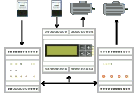 System is designated to measure and control energy consumption. Its function is based on a electrometer impulse output measuring and processing. Device is connected to electrometer by separating module. Real-time energy consumption are calculated from electrometer impulse output. This calculation are processed further by controlling algorithms, which result is power-off commands for previously defined consumer device/machine. This avoids energy consumption level overrun. Output modules: The advantage of maximum power demand controller is that beside local controlling of its own outputs it has a possibility to send energy consumption control signals for farther distances by RS-485 serial link to output modules. RS-485 connection means considerable saving of total cabling. Input modules: System also enables 12 different energy consumption measures, summation of individual measures into one virtual measure is possible. Energy consumption posts can be distant from central unit, if yes input modules are used for measuring. Input module are connected to central unit by same RS-485 link as output modules. Measure period synchronisation is possible to execute on any of connected input modules or on central unit - maximum power demand controller. Beside electric energy consumption measurement system enables measuremets of other types of energy (gas, water, fume, heat...), if there is impulse output present, informing about real-time consumption. Central unit involves microcomputer which control all system functionality. User interface consist of 2-line display and 4 navigating buttons. Actual consumption, time, control state, reached maximum can be shown on the display. Some configuration settings can be made by user interface also. Microcontroller involves back-up memory where it stores measured values of consumption, control action data and other values. There is serial link RS232/485 also available which enables connection to PC. In PC measured data can be archived and analysed by table or graph representation. Technical resources Main element of the system is microcontroller with firmware to measure and control energy consumption. 15 output modules are possible to connect to this system enabling topologigally distant consumer control. 1. Main microcontroller It is a solid device placed in a plastic box enabling comfortable install to cutout boxes 35mm DIN fixation. Also suitable to install to standard fuseboxes. Technical specifications: ◘ CPU unit with 32 or 128 kB backup memory ◘ 4 digital optically separated inputs 5 - 24 V = ◘ 8 digital optically separated transistor outputs max. 30 V= /1A ◘ 2 communication links RS 485 a RS 232 ◘ user interface including 2-line LCD display and 4 navigating buttons ◘ external power supply 9 - 30 V=, cca 1,5 W 2. Output module It is designated to distant power off of selected consumers due to control commands received from main mocrocontroller received by RS485 serial link. Technical specifications: ◘ 4 digital optically separated transistor outputs max. 30 V= /1A ◘ communication link RS 485, 1200Bd ◘ external power supply 9 - 30 V=, cca 50 mA 3. Power supply: Power supply 2x 9V=, 5VA is shipped with the device. It is placed in a plastic box with 35mm DIN fixation. It can be use for main microcontroller, output module, relays and other devices power supply if summation of energy imports not exceeds 5VA. Summation: 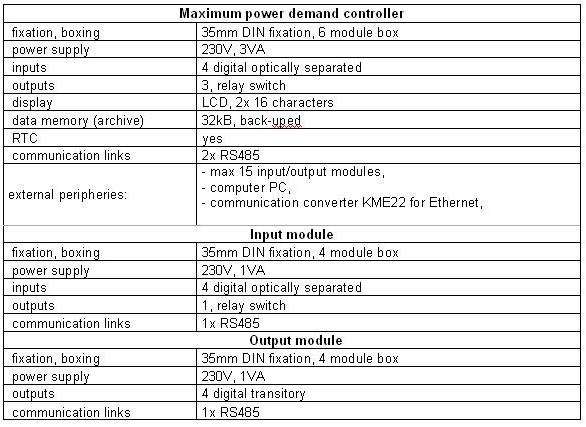 |

